Setting up closed loop for the first time? Or Changing lambda sensor to a new location? Proper delay must be introduced for correct closed loop operation.
The dual lambda setup:
- 4.9 LSU Lambda sensor per bank located after cylinder bank collector,
- Sensors are free air calibrated,
- Connected to LTCD controller,
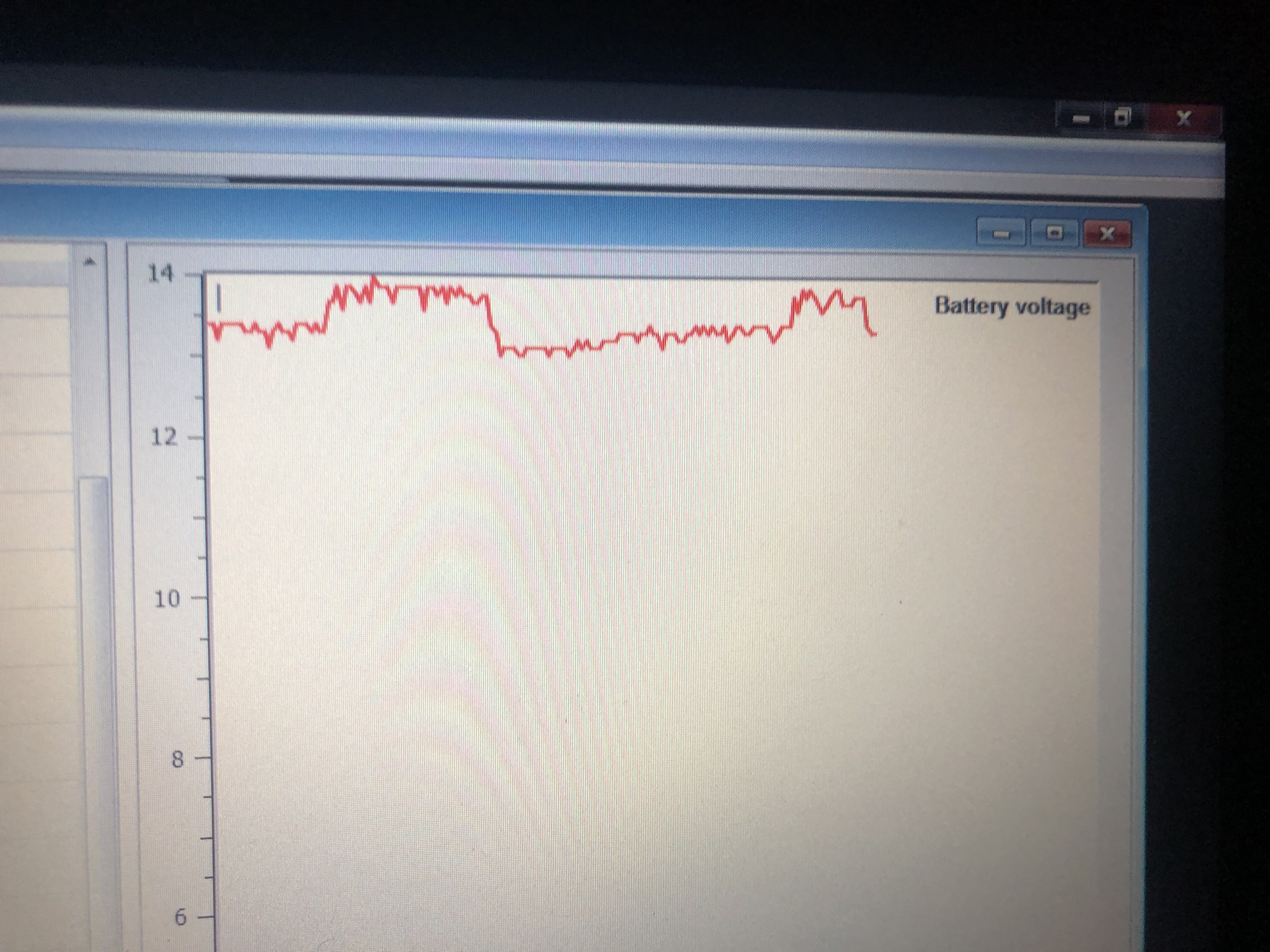
- Lambda heating turns on at 240 seconds in order to prevent sensor breaking from moisture.
The single lambda setup:
- NTK Lambda sensor located at X-pipe collector,
- 1600mm distance from cylinder heads,
- Sensor free air calibrated,
- Connected to LTCD NTK controller.
The methodology:
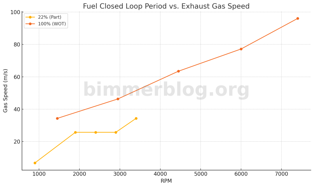
- The baseline for exhaust gas speed was simulated both WOT and 22% of throttle opening,
- Approximated average gas speeds,
- Delay was was calculated based on the sensor location (1600mm),
- Less aggressive Trim Gain (80% -> 37%) was introduced on idle region to prevent oversampling and oscillation,
- More frequent sampling rate was applied to compensate for less aggressive Trim Gain,
- Decreased max. negative trim value (-5%) to protect engine from faulty sensor(s),
- Test drive and post analysis with 200hz sampling rate for Lambda sensor was applied.
The chart below is further optimized Fuel Closed Loop Period for full rev range. Since gas velocity is very low at idle due to aggressive cam setup, Closed Loop can be turned on e.g. at 1300rpm. This eliminates the need for increased delay on idle, and can smoothen transition from idle to cruising, and vice versa. Since 4.9 lambda sensors are prone to break in non-cat engines, delayed heater activation is used. No oscillation observed with the following delays.
Note: The new setup will be utilizing three lambda sensors: one per bank, and third one in the x-pipe collector to measure sum. This is to prevent accidental 4.9 lambda sensor malfunctioning, where sensor can show too rich mixture before breaking for good.